Feedback Devices - ERD
MODEL ERD ENCODER RESOLVER DIGITIZER
Download ERD Manual (Rev E) (PDF) | (DOCX)
PRELIMINARY USER'S GUIDE
Model ERD converts brushless resolver signals to two phase quadrature signals similar to the signals generated by an incremental encoder. A once-per-rev index pulse is also generated. These three signals are available on complementary TTL compatible open collector outputs, which are internally "pulled up" to an external 5 volts through 1,000 ohms.
Incremental resolution is set at 1,024 cycles per revolution. Common quadrature detection circuitry will decode this to provide 4,096 counts per revolution.
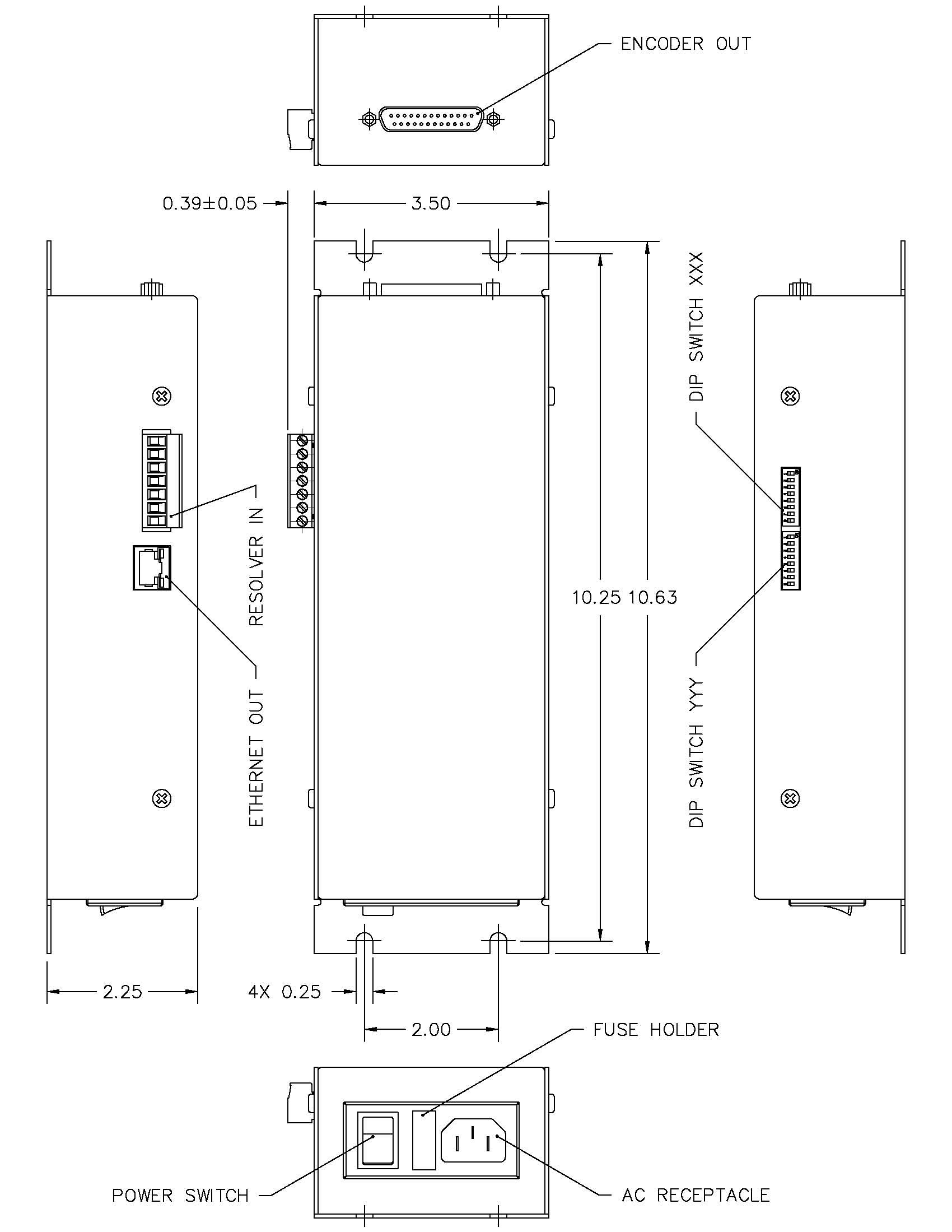
MOUNTING DIMENSIONS
Specifications |
|
Power |
95-264 VAC,47-63Hz, 30W |
Isolated interface |
5VDC @ 150 mA |
Operating temperature |
0 to 60°C |
Maximum velocity |
40 rev/sec |
Accuracy |
.3° |
Resolver Output |
7VRMS, 1kHz, 100mA |
Encoder Outputs |
(open collector, 1k to +5V) |
Sink current |
30 mA |
Quadrature |
90°±10% |
Index pulse |
At 90° ½ width of channel A |
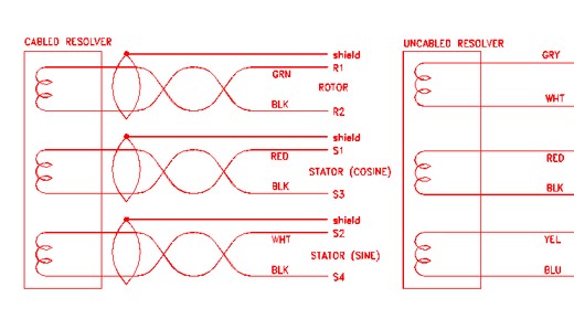
RESOLVER CONNECTION
Cabling from the resolver is to be connected to the removable screw terminal connector of the ERD, according to the wire color assignments below. Cable conductors should be stripped back 3/16 inch or so, inserted into the appropriate wire aperture, and screwed down. Verify proper insertion with a light pull test. Cable conductors are 22AWG twisted pair.
Resolver |
Standard Resolver |
Vacuum & Radiation |
w/ Cable |
|
|
|
|
Rotor R1 |
Red/White |
Gray |
Green |
Rotor R2 |
Black/White |
White |
BlackGreen |
|
|
|
|
Stator S1 |
Red |
Red |
Red |
Stator S3 |
Black |
Black |
BlackRed |
Stator S2 |
Yellow |
Yellow |
White |
Stator S4 |
Blue |
Blue |
BlueWhite |
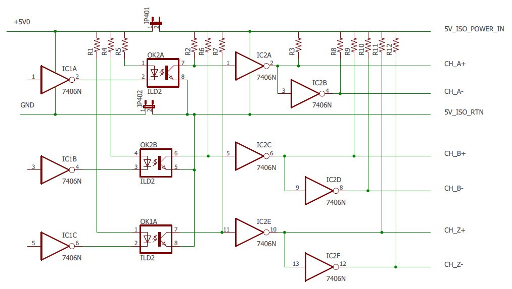
ENCODER CONNECTIONS
Optically isolated incremental encoder signals are available on the 25 pin "D" connector on the end of the ERD. Signal assignments are listed by pin number below. Note that the optical interface requires application of +5VDC at up to 50 mA to power the interface. This power comes in on the 5V_ISO_POWER_IN connector on pin 24 and 5V_ISO_RTN on pin 14-19.
Signal |
Pin Number |
Channel A+ |
1 |
Channel A- |
2 |
Channel B+ |
3 |
Channel B- |
4 |
Channel Z+ |
5 |
Channel Z- |
6 |
Shield |
8 |
5V ISO RTN |
14-19 |
+5V ISO POWER IN |
24 |
NON optically isolated incremental encoder signals are available on the 25 pin "D" connector on the end of the ERD. In this mode the ERD supplies the power needed to run the interface plus and extra 100ma to power external equipment. Note that in this configuration the interface is no longer optically isolated. Signal assignments are listed by pin number below. Note that the user must remove the four side screws and detach the ERD cover. Locate circuit board jumpers JU401 and JU402 near the encoder connector. Install the jumper block bridging the two pins of jumper JU402 to connect encoder ground to ERD power supply ground. Install jumper JU401 to connect ERD 5 volts to the encoder connector.
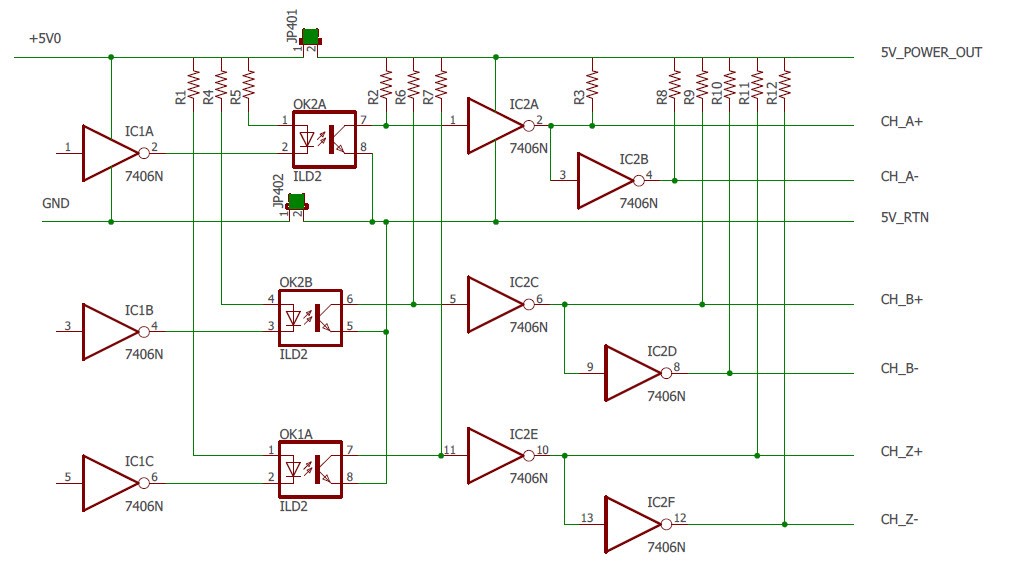
See diagram below to show the Jumper locations.
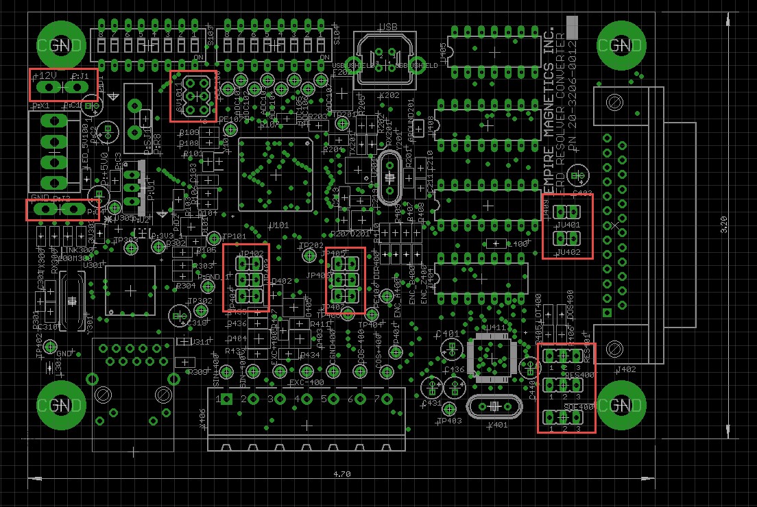
Note: Using the internal power supply to drive output signals defeats the optical isolation.
Signal |
Pin Number |
Channel A+ |
1 |
Channel A- |
2 |
Channel B+ |
3 |
Channel B- |
4 |
Channel Z+ |
5 |
Channel Z- |
6 |
Shield |
8 |
5V RTN |
14-19 |
+5V POWER OUT |
24 |
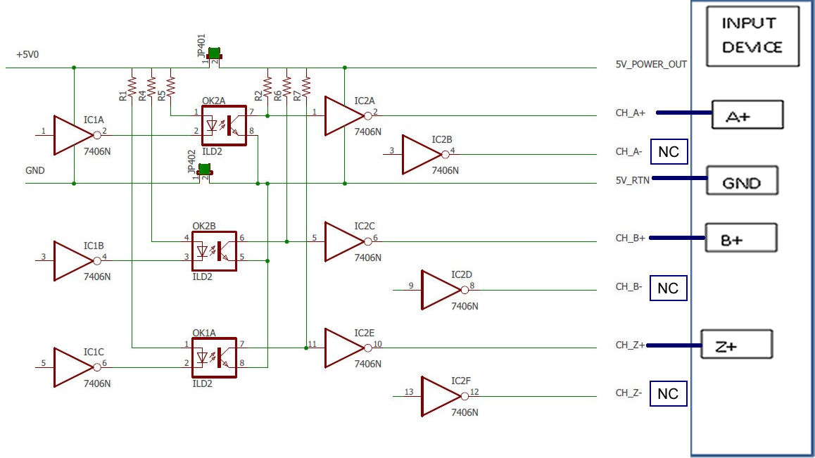
OPEN COLLECTOR non optically isolated incremental encoder signals are available on the 25 pin "D" connector on the end of the ERD. In this mode the ERD supplies the power needed to run the interface plus and extra 100ma to power external equipment. Note that in this configuration the interface is no longer optically isolated. The output signals are compatible with 24 VDC inputs on PLCs or other high voltage input devices. The outputs A+, B+, and Z+ are open collector outputs capable of sinking 30ma at up to 30 VDC. The other outputs should be left unconnected. Connect 5V RTN to the input device circuit ground. Signal assignments are listed by pin number below. Note that the user must order the unit with this configuration since this configuration cannot be created in the field.
Signal |
Pin Number |
Channel A+ (30 volts max) |
1 |
Channel A- no connect (NC) |
2 |
Channel B+ (30 volts max) |
3 |
Channel B- no connect (NC) |
4 |
Channel Z+ (30 volts max) |
5 |
Channel Z- no connect (NC) |
6 |
Shield |
8 |
5V RTN |
14-19 |
+5V POWER OUT |
24 |
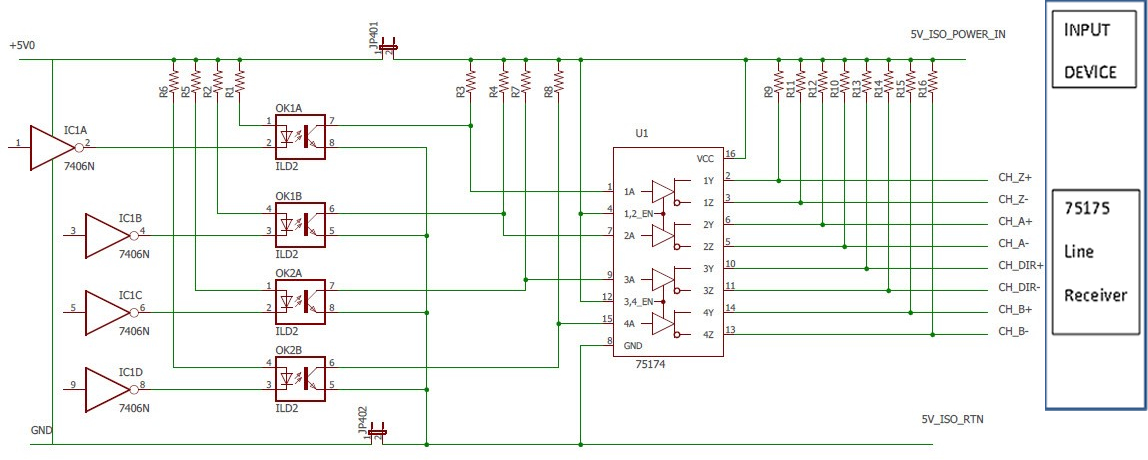
Optically isolated differential incremental encoder signals are available on the 25 pin "D" connector on the end of the ERD. Signal assignments are listed by pin number below. Note that the optical interface requires application of +5VDC at up to 50 mA to power the interface. This power comes in on the 5V_ISO_POWER_IN connector on pin 24 and 5V_ISO_RTN on pin 14-19. Note that the user must order the unit with this configuration since this configuration cannot be created in the field. The input device must contain a 75175 differential line receiver chip.
Signal |
Pin Number |
Channel A+ |
1 |
Channel A- |
2 |
Channel B+ |
3 |
Channel B- |
4 |
Channel Z+ |
5 |
Channel Z- |
6 |
Shield |
8 |
Channel DIR+ |
11 |
Channel DIR- |
12 |
5V ISO RTN |
14-19 |
+5V ISO POWER IN |
24 |
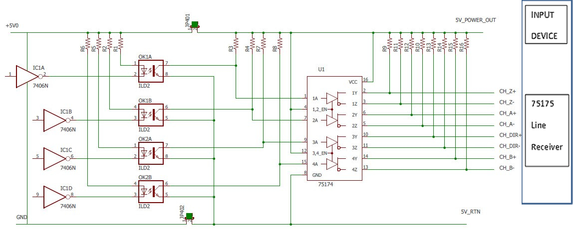
NON optically isolated differential incremental encoder signals are available on the 25 pin "D" connector on the end of the ERD. In this mode the ERD supplies the power needed to run the interface plus and extra 100ma to power external equipment. Note that in this configuration the interface is no longer optically isolated. Signal assignments are listed by pin number below. Note that the user must order the unit with this configuration since this configuration cannot be created in the field. The input device must contain a 75175 differential line receiver chip.
Signal |
Pin Number |
Channel A+ |
1 |
Channel A- |
2 |
Channel B+ |
3 |
Channel B- |
4 |
Channel Z+ |
5 |
Channel Z- |
6 |
Shield |
8 |
Channel DIR+ |
11 |
Channel DIR- |
12 |
5V RTN |
14-19 |
+5V POWER OUT |
24 |
POSITION READOUT
The ERD supports two options to allow a computer to readout the position. The user must choose which option is to be installed at the factory at the time of purchasing. The option cannot be changed in the field.
Option 1: WEB SERVER ETHERNET DATA OPTION
Model EDR provides a Web Client server that reports a position as a string of ASCII digits in html format. At power on the EDR reads the absolute position of the resolver and then keeps track of the position until the next power cycle. The Ethernet device address is 192.168.xxx.yyy where xxx and yyy are specified on the dip switches on the box. Your IT administrator will assign you values for xxx and yyy. To verify the WEB SERVER OPTION invoke a web browser (iexplorer, Firefox, etc ) and enter the Ethernet address 192.168.xxx.yyy as the URL. The position of the EDR should appear as ASCII on your screen.
If your IT administrator wants a different IP address than 192.168 the address must be requested at the time of the order. The 192.168 part of the Ethernet address cannot be changed in the field.
Option 2: TCP/IP ETHERNET DATA OPTION
Model EDR provides a TCP/IP connection that upon receipt of a “p” command reports a position as a string of ASCII digits terminated with a carriage return/line feed. At power on the EDR reads the absolute position of the resolver and then keeps track of the position until the next power cycle. The receipt of a “z” command will make the current position zero. The receipt of a “x” command will close the Ethernet socket connection. The Ethernet device address is 192.168.xxx.yyy where xxx and yyy are specified on the dip switches on the box. Your IT administrator will assign you values for xxx and yyy.
To verify the TCP/IP option you will need a small program written in C to open a socket connection and send/receive data to the EDR unit. The C program will need to contain the Ethernet address of the EDR unit (192.168.xxx.yyy). See sample code written using Visual studio 2013 shown in Appendix B. This is a simple console application. If your IT administrator wants a different IP address than 192.168 the address must be requested at the time of the order. The 192.168 cannot be changed in the field. The value 192.168 must also be changed in the C program below to the value assigned by the IT administrator.
APPENDIX B
// TCP send receive.cpp: Defines the entry point for the console application.
#include"stdafx.h"
#define_WINSOCK_DEPRECATED_NO_WARNINGS
// Create a TCP socket
#include<stdio.h>
#include<winsock2.h>
#pragmacomment(lib,"ws2_32.lib") // Winsock Library
int main(intargc, char *argv[])
{
WSADATA wsa;
SOCKET s;
structsockaddr_in server;
char *message, server_reply[10000];
int recv_size;
int xx;
printf("\nInitialising Winsock...");
if (WSAStartup(MAKEWORD(2, 2), &wsa) != 0)
{
printf("Failed. Error Code : %d", WSAGetLastError());
return 1;
}
printf("Initialised.\n");
// Create a socket
if ((s = socket(AF_INET, SOCK_STREAM, 0)) == INVALID_SOCKET)
{
printf("Could not create socket : %d", WSAGetLastError());
}
printf("Socket created.\n");
server.sin_addr.s_addr = inet_addr("192.168.1.7");
server.sin_family = AF_INET;
server.sin_port = htons(255);
// Connect to remote server
if (connect(s, (structsockaddr *)&server, sizeof(server)) < 0)
{
puts("connect error");
char e = getchar();
return 1;
}
puts("Connected");
for (xx = 0; xx < 2000; xx++)
{
// Send some data
message = "p";
if (send(s, message, strlen(message), 0) < 0)
{
puts("Send failed");
char d = getchar();
return 1;
}
puts("Data Send\n");
// Receive a reply from the server
if ((recv_size = recv(s, server_reply, 10000, 0)) == SOCKET_ERROR)
{
puts("recv failed");
}
printf(" size %d\n", recv_size);
puts("Reply received");
// Add a NULL terminating character to make it a proper string before printing
server_reply[recv_size] = '\0';
puts(server_reply);
puts("press key to continue\n");
printf("xx %d\n", xx);
}
// Tell the EDR to close its socket.
message = "x";
if (send(s, message, strlen(message), 0) < 0)
{
puts("Send failed");
char d = getchar();
return 1;
}
puts("Data Send x\n");
// disconnect socket
// cleanup
closesocket(s);
WSACleanup();
puts("press key to continue\n");
char c = getchar();
return 0;
}
TROUBLESHOOTING
Electronic switching motor drives create large amounts of electrical noise which may occasionally generate position errors in electronic feedback devices. Any accumulation of noise related positioning error may be eliminated by executing a "Go Home" instruction (GH command). This command should be included in repetitive operations where possible to insure accuracy.
If the polarity of the closed loop position report is negative, exchange red and black motor wires to reverse motor direction, or exchange red and black resolver wires to reverse encoder output direction. If it is not within a few counts, the motor controller is not getting ERD signals. Verify that the encoder interface is getting 5 volt power from the control. Verify proper resolver and encoder connections.
Bad resolver coupling and mounting, or even low motor current setting can contribute to position report error.
ERD Manual Quick Links
Mounting Dimensions
Resolver Connection
Encoder Connections
- Optically isolated incremental encoder signals
- NON optically isolated incremental encoder signals
- OPEN COLLECTOR non optically isolated incremental encoder signals
- Optically isolated differential incremental encoder signals are available
- NON optically isolated differential incremental encoder signals
Position Readout (important!)
Appendix B
Troubleshooting
Download ERD Manual (Rev E) (PDF) | (DOCX)
