Feedback Devices - ERD
MODEL ERD - STANDARD
ENCODER RESOLVER DIGITIZER USER'S GUIDE
Table of Contents
| 1 | REVISION HISTORY |
| 1.1 | April 13, 2020 separate into three different documents: standard, open collector, differential output |
| 2 | ERD FEATURES |
| 3 | MOUNTING DIMENSIONS |
| 4 | SPECIFICATIONS |
| 5 | RESOLVER CONNECTION |
| 5.1 | Resolver Cable Color Codes |
| 5.2 | Cabled Resolver Connection |
| 6 | ENCODER CONNECTION |
| 6.1 | Optically Isolated Incremental Encoder Signals |
| 6.2 | NON Optically Isolated Incremental Encoder Signals |
| 6.3 | Diagram Showing The Jumper Locations |
| Note: Using the internal power supply to drive output signals defeats the optical isolation | |
| 7 | POSITION SAVED ON LOSS OF POWER |
| 8 | POSITION READOUT |
| 8.1 | TCP/IP Ethernet Data |
| 8.2 | ‘p’ Command |
| 8.3 | ‘z’ Command |
| 8.4 | ‘x’ Command |
| 8.5 | ‘d-‘ Command |
| 8.6 | ‘h’ Command |
| 8.7 | ‘odddd’ Command |
| 8.8 | The Ethernet Device Address |
| 8.9 | ‘nAAA’ Command |
| 8.10 | ‘wBBB’ Command |
| 9 | VERIFY THE TCP/IP OPTION |
| 10 | APPENDIX B – VISUAL C++ SAMPLE CODE |
| 11 | TROUBLESHOOTING |
| 11.1 | Cumulative Electrical Noise |
| 11.2 | Non Cumulative Electrical Noise |
| 11.3 | Polarity Reversal |
| 11.4 | Poor Mechanical Connections |
1 REVISION HISTORY
1.1 April 13, 2020 separate into three different documents: standard, open collector, differential output.
2 ERD FEATURES
For environments like vacuum and radiation, encoders are not robust enough to withstand the rigors imposed by these demanding situations. Since resolvers have a physical construction similar to that of electric motors, resolvers can be used where encoders fail. However; there are many more control systems available that are encoder compatible than there are that have resolver compatibility. To bridge this difference between encoders and resolvers, Empire Magnetic Inc. has developed an electronics interface (ERD) that solves this problem. An additional feature provides absolute positional information via an Ethernet interface.
The ERD provides excitation signals to a resolver, and decodes the sine and cosine return signals to provide position feedback.
The output of the ERD is in two formats. The first is incremental, encoder type A, B, Z suitable for quadrature detection. The standard product is TTL compatible, 1024 count pre quadrature, 4096 count post quadrature. The Z marker pulse happens once per resolver cycle. When connected with a single speed resolver, there is one very narrow marker pulse per revolution.
The second output is an up/down counter intended to provide absolute position over a range of +/- 2 ^31 or +/- 2147483648 counts. At 4096 counts per revolution that is +/- 524,288 revolutions. Resolutions of 8192 and 16,384 counts per revolution are available.
The up/down counter output is available over Ethernet. Commands to set a zero, read position, read velocity, or install an offset count are provided. Sample code written in visual studio is also available.
Auto save feature: The ERD has an auto save that captures the last known absolute 31 bit position in the event of power loss. If the mechanics move less than one revolution when the AC power goes off the unit will compute the correct 31 bit absolute position when power is restored. This feature uses FRAM technology and can handle over ten trillion power cycles.
The ERD is powered by a universal power supply which operates from Line AC voltages 95 to 264 VAC 50/60hz.
The ERD is a single axis unit intended to operate with one resolver. The Ethernet address can be changed to provide individual addresses.
This set of electronics is intended to be operating in a typical industrial or lab environment, where the resolvers are on long cables leading to environmental areas such as vacuum chambers.
Simulated Incremental Encoder interface
Model ERD converts brushless resolver signals to two phase quadrature signals similar to the signals generated by an incremental encoder. A once-per-rev index pulse is also generated. These three signals are available on complementary TTL compatible open collector outputs, which are internally "pulled up" to an external 5 volts through 1,000 ohms.
Incremental resolution is set at 1,024 cycles per revolution. Common quadrature detection circuitry will decode this to provide 4,096 counts per revolution. Additional resolutions are available upon request.
The simulated encoder interface is available in two flavors. Optically isolated where the device receiving the quadrature signals must supply +5 VDC power to the ERD. Non optically isolated where the ERD supplies +5VDC power to the quadrature output stage resulting in TTL compatible outputs.
3 MOUNTING DIMENSIONS
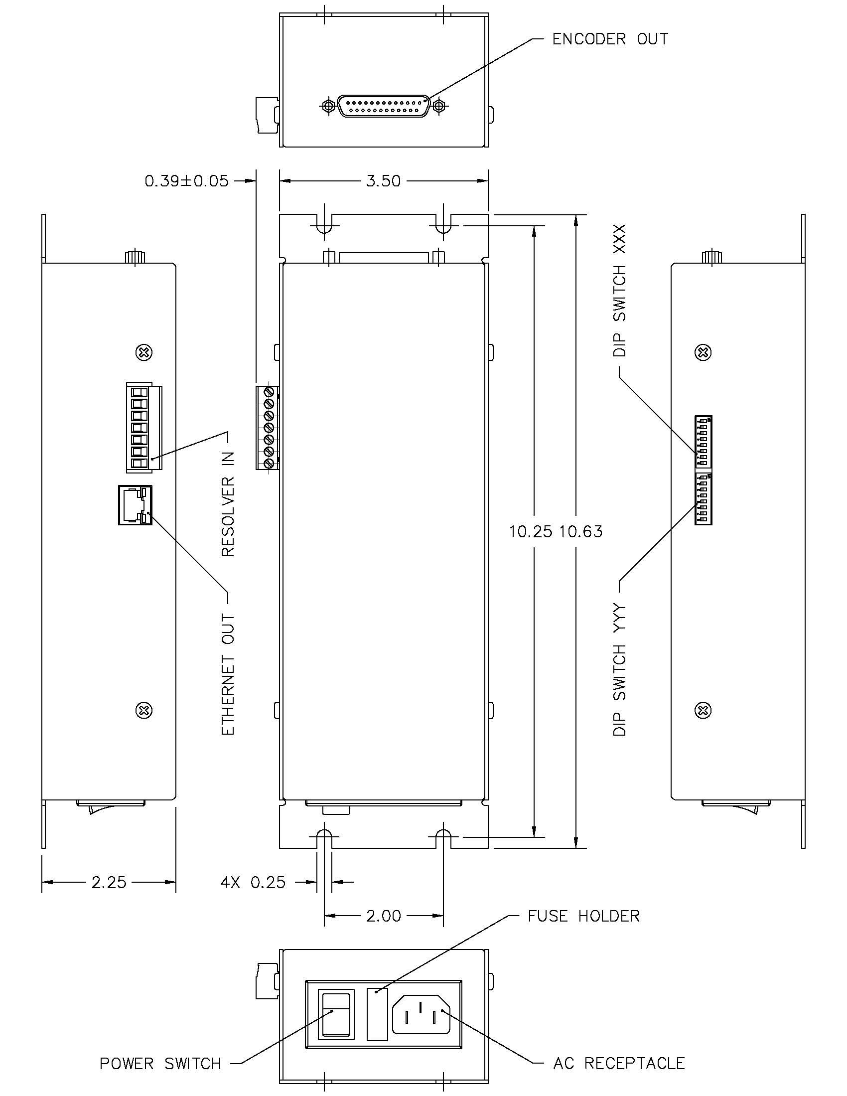
4 SPECIFICATIONS
Specifications |
|
Power |
95-264 VAC,47-63Hz, 30W |
Isolated interface |
5VDC @ 150 mA |
Operating temperature |
0 to 60°C |
Maximum velocity |
40 rev/sec |
Accuracy |
.3° |
Resolver Output |
7VRMS, 1kHz, 100mA |
Encoder Outputs |
(open collector, 1k to +5V) |
Sink current |
30 mA |
Quadrature |
90°±10% |
Index pulse |
At 90° ½ width of channel A |
|
|
5 RESOLVER CONNECTION
Cabling from the resolver is to be connected to the removable screw terminal connector of the ERD, according to the wire color assignments below. Cable conductors should be stripped back 3/16 inch or so, inserted into the appropriate wire aperture, and screwed down. Verify proper insertion with a light pull test. Cable conductors are 22AWG twisted pair.
5.1 Resolver Cable Color Codes
Resolver |
Standard Resolver |
Vacuum & Radiation |
w/ Cable |
|
|
|
|
Rotor R1 |
Red/White |
Gray |
Green |
Rotor R2 |
Black/White |
White |
BlackGreen |
|
|
|
|
Stator S1 |
Red |
Red |
Red |
Stator S3 |
Black |
Black |
BlackRed |
Stator S2 |
Yellow |
Yellow |
White |
Stator S4 |
Blue |
Blue |
BlueWhite |
5.2 Cabled Resolver Connection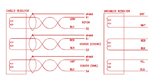
6 ENCODER CONNECTION
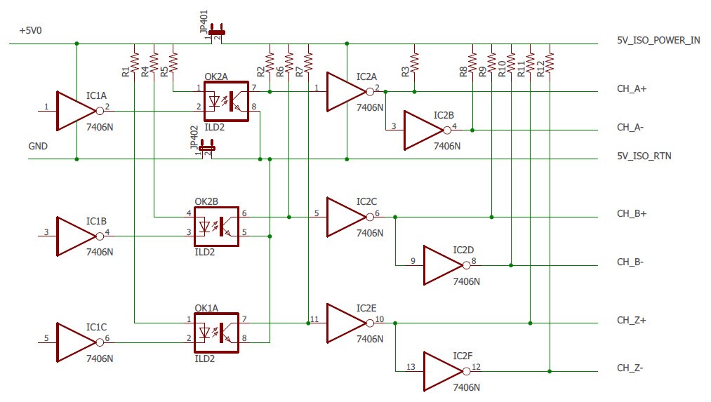
6.1 Optically isolated incremental encoder signals
Are available on the 25 pin "D" connector on the end of the ERD. Signal assignments are listed by pin number below. Note that the optical interface requires application of +5VDC at up to 50 mA to power the interface. This power comes in on the 5V_ISO_POWER_IN connector on pin 24 and 5V_ISO_RTN on pin 14-19.
Signal |
Pin Number |
Channel A+ |
1 |
Channel A- |
2 |
Channel B+ |
3 |
Channel B- |
4 |
Channel Z+ |
5 |
Channel Z- |
6 |
Shield |
8 |
5V ISO RTN |
14-19 |
+5V ISO POWER IN |
24 |
6.2 NON optically isolated incremental encoder signals
Are available on the 25 pin "D" connector on the end of the ERD. In this mode the ERD supplies the power needed to run the interface plus and extra 100ma to power external equipment. Note that in this configuration the interface is no longer optically isolated. Signal assignments are listed by pin number below. Note that the user must remove the four side screws and detach the ERD cover. Locate circuit board jumpers JU401 and JU402 near the encoder connector. Install the jumper block bridging the two pins of jumper JU402 to connect encoder ground to ERD power supply ground. Install jumper JU401 to connect ERD 5 volts to the encoder connector.
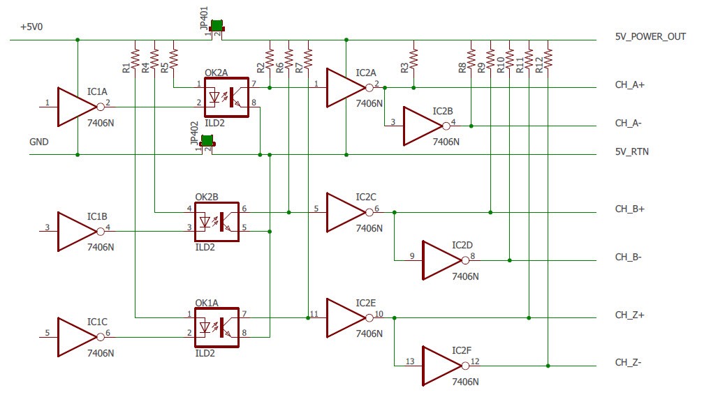
6.3 Diagram Showing the Jumper Locations
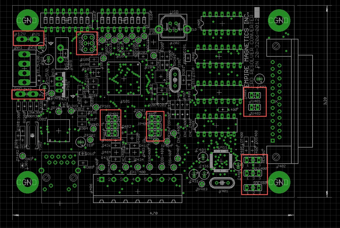
Note: Using the internal power supply to drive output signals defeats the optical isolation.
Signal |
Pin Number |
Channel A+ |
1 |
Channel A- |
2 |
Channel B+ |
3 |
Channel B- |
4 |
Channel Z+ |
5 |
Channel Z- |
6 |
Shield |
8 |
5V RTN |
14-19 |
+5V POWER OUT |
24 |
7 POSITION SAVED ON LOSS OF POWER
When the ERD detects an impending loss of power it saves the current position into FRAM and halts the processor. When the unit powers up it will recall the last position from the FRAM and adjust the position to compensate for any movement of the resolver that occurred within one revolution of the resolver. If the resolver moves more than one revolution when power is off the position will not be correct. This works well with systems that are equipped with mechanical brakes that on loss of power allow the motor to move a little bit before they mechanically clamp the shaft in place.
The FRAM supports 10 trillion reads and writes without loss of information.
8 POSITION READOUT
8.1 TCP/IP Ethernet Data
Model EDR provides a TCP/IP connection that processes several Ascii character commands:
8.2 ‘p’ Command
Reports a position as a string of ASCII digits terminated with a carriage return/line feed. At power on the EDR reads the absolute position of the resolver that was stored in the FRAM and then keeps track of the position until the next power cycle.
8.3 ‘z’ Command
Will make the current position zero.
8.4 ‘x’ Command
Will close the Ethernet socket connection.
8.5 ‘d-‘ Command
Will cause the position to be negated before it is reported.
8.6 ‘h’ Command
Will set the position to zero on the next index marker pulse.
8.7 ‘odddd’ Command
Sets a position offset. The position is given as a signed decimal number following the character ‘o’. Example is o+500. This means that 500 will be added to the position before it is reported.
8.8 The Ethernet Device Address
Default is 192.168.xxx.yyy where xxx and yyy are specified on the dip switches on the box. Your IT administrator will assign you values for xxx and yyy. The values on the dip switches are in binary and switch 1 on each dip switch is the most significant bit. If the switch is up it is a ‘1’ and if it is down it is a ‘0’. So if XXX is set to 0000001 and YYY is set to 0000111 the address of the unit is 192.168.1.7
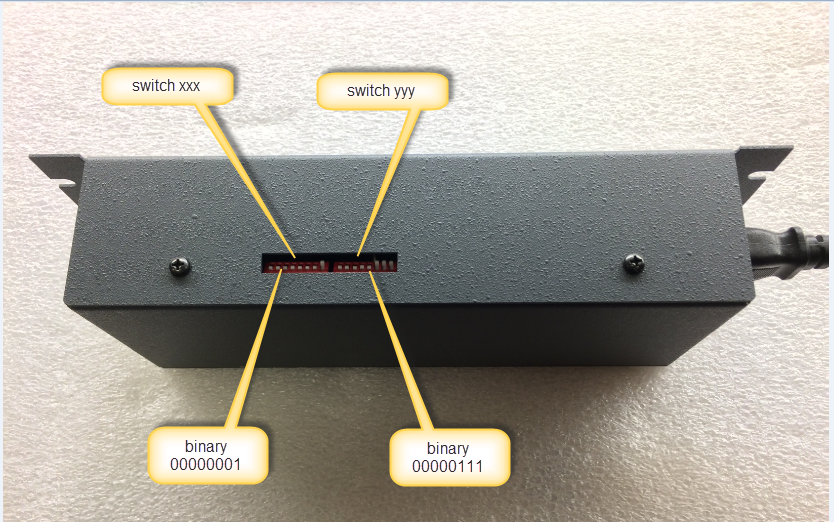
If you want 192.168.10.47 then XXX is 0001010 and YYY is 101111 since 10 in binary is 0001010 and 47 in binary is 101111.
8.9 ‘nAAA’ Command
Will let you change the value of the 192.
8.10 ‘wBBB’ Command
Will let you change the value of the 168. Once you change these values the unit will reset and respond to the new IP address. You have to hit the reset button to restore the values to 192.168
9 VERIFY THE TCP/IP OPTION
You will need a small program written in C to open a socket connection and send/receive data to the EDR unit.
The C program will need to contain the Ethernet address of the EDR unit (192.168.xxx.yyy). See sample code written using Visual studio 2013 shown in Appendix B. This is a simple console application.
If your IT administrator wants a different IP address than 192.168 the address can be changed using the nAAA and wBBB commands. The values for nAAA and WBBB are stored in the non-volatile memory so they are retained if you cycle power.
APPENDIX B
// TCP send receive.cpp : Defines the entry point for the console application. //
#include "stdafx.h"
#define _WINSOCK_DEPRECATED_NO_WARNINGS
/* Create a TCP socket */
#include<stdio.h> #include<winsock2.h>
#pragma comment(lib,"ws2_32.lib") //Winsock Library
int main(int argc, char *argv[]) { WSADATA wsa; SOCKET s; struct sockaddr_in server; char *message, server_reply[10000]; int recv_size;
int xx;
printf("\nInitialising Winsock..."); if (WSAStartup(MAKEWORD(2, 2), &wsa) != 0) { printf("Failed. Error Code : %d", WSAGetLastError()); return 1; }
printf("Initialised.\n");
//Create a socket if ((s = socket(AF_INET, SOCK_STREAM, 0)) == INVALID_SOCKET) { printf("Could not create socket : %d", WSAGetLastError()); }
printf("Socket created.\n");
server.sin_addr.s_addr = inet_addr("192.168.1.7"); server.sin_family = AF_INET; server.sin_port = htons(255);
//Connect to remote server if (connect(s, (struct sockaddr *)&server, sizeof(server)) < 0) { puts("connect error"); char e = getchar();
return 1; }
puts("Connected");
for (xx = 0; xx < 2000; xx++) {
//Send some data message[0] = "p"; if (send(s, message, strlen(message), 0) < 0) { puts("Send failed"); char d = getchar(); return 1; } puts("Data Send\n");
//Receive a reply from the server if ((recv_size = recv(s, server_reply, 10000, 0)) == SOCKET_ERROR) { puts("recv failed"); }
printf(" size %d\n", recv_size); puts("Reply received");
//Add a NULL terminating character to make it a proper string before printing server_reply[recv_size] = '\0'; puts(server_reply);
puts("press key to continue\n"); printf("xx %d\n", xx);
} // tell the EDR to close its socket. message = "x"; if (send(s, message, strlen(message), 0) < 0) { puts("Send failed"); char d = getchar(); return 1; } puts("Data Send x\n");
// disconnect socket
// cleanup closesocket(s); WSACleanup();
puts("press key to continue\n"); char c = getchar(); return 0; }
|
TROUBLESHOOTING
11.1 Cumulative Electrical Noise
Electronic switching motor drives create large amounts of electrical noise which may occasionally generate position errors in electronic feedback devices. Any accumulation of noise related positioning error may be eliminated by having the motor controller execute a "Go Home" instruction (GH command). This command should be included in repetitive operations where possible to insure accuracy.
11.2 Non Cumulative Electrical Noise
You may experience a jitter of a few counts when the drive is power on. This is because the switch-mode drive powering the motor coupes high frequency noise to the motor shaft which needs to find a way back to the ground the drive uses. Results improve if you directly ground the case of the motor resolver to the same earth ground used by the drive so this noise does not try to find its way back to the drive through the ERD ‘s electronics.
11.3 Polarity Reversal
If the polarity of the closed loop position report is negative, exchange red and black motor wires to reverse motor direction, or exchange red and black resolver wires to reverse encoder output direction. If it is not within a few counts, the motor controller is not getting ERD signals. Verify that the encoder interface is getting 5 volt power from the control. Verify proper resolver and encoder connections.
11.4 Poor Mechanical Connections
Bad resolver coupling and mounting or even low motor drive current settings can contribute to position report error.
ERD Manual Quick Links
Mounting Dimensions
Resolver Connection
Encoder Connections
- Optically isolated incremental encoder signals
- NON optically isolated incremental encoder signals
- OPEN COLLECTOR non optically isolated incremental encoder signals
- Optically isolated differential incremental encoder signals are available
- NON optically isolated differential incremental encoder signals
Position Readout (important!)
Appendix B
Troubleshooting
Download ERD Manual (PDF) | (DOCX)
